Developing safe, energy-efficient ambient lighting systems for high-traffic hospitality venues, historic preservation sites, and residential spaces requires replacing open-flame combustion sources with precise electronic alternatives. The modern, commercial-grade LED electronic candle serves as the primary technical solution to achieve this goal, removing fire hazards, smoke particulates, and messy wax cleanup. By integrating microcontrolled pulse-width modulation (PWM) drivers, low-voltage electrochemical cells, and specialized optical diffusion lenses, these solid-state devices recreate the natural movement and warm color spectrum of real candle flames while maintaining thousands of hours of continuous operational runtime.
Kinematics of Fire Simulation and Pseudo-Random Algorithm Drivers
The primary challenge when designing an electronic alternative to a real wax candle is accurately mimicking the organic, unpredictable movement of a natural flame. Human eyes are highly attuned to repetitive movements; simple, fixed electronic blinking patterns are quickly noticed and break the illusion of realism.
To solve this, advanced electronic candles utilize a dedicated, low-power integrated circuit (IC) or microcontroller programmed with a Linear Feedback Shift Register (LFSR) algorithm. This software configuration creates a pseudo-random number sequence that continuously alters the electrical current traveling to the light-emitting diode. Instead of a basic cycle, the algorithm updates the diode's power levels thousands of times per second, shifting between 256 distinct dimming levels to create subtle changes in light output that mimic the natural buffeting of air currents across a burning wick.
Mechanical Flame Elements vs. Static Optical Waveguides
Manufacturers divide flame simulation technology into two primary structural categories:
- Moving-Wick Kinematic Assemblies: This design mounts a flame-shaped plastic blade on a delicate, low-friction metal wire pivot. A small electromagnetic coil at the base pulses at irregular intervals, pushing a tiny magnet attached to the blade. This physical movement deflects a stationary upward-projecting LED beam, creating organic moving shadows on adjacent walls just like a shifting flame.
- Multi-Diode Static Waveguides: This alternative eliminates all moving parts, which can wear out and make mechanical noise over time. It utilizes a cluster of 3 to 5 separate LED dies placed inside a frosted silicone or acrylic tube. The internal microcontroller alters the power level of each individual chip in a rolling cycle, shifting the physical center of light up and down inside the lens to mimic a flickering flame electronically.
Photometric Engineering and Spectral Color Tuning
Recreating the visual warmth of burning wax requires selecting and tuning the proper solid-state semiconductor chemistry. A standard household light bulb typically operates at a crisp 2700K to 3000K color temperature, which looks far too cold and artificial when placed inside an electronic candle shell.
A real chemical wood or cotton wick flame glows within a warm spectral range of 1600K to 1900K, created by the thermal radiation of microscopic soot particles. To match this distinct look, electronic candles use specialized gallium phosphide (GaP) or indium gallium aluminum phosphide (InGaAlP) semiconductor dies that produce a true amber-yellow light, centered at a dominant wavelength of 589 to 595 nanometers. Advanced multi-color versions combine these amber chips with a secondary warm-white diode. By blending these two light paths, the system can display a deep orange-red glow near the base of the simulated wick while transitioning into a brighter, warm-yellow point at the peak of the flame.
Performance Specifications and Electrochemical Capacity Tiers
Specifying commercial lighting equipment for hotels, restaurants, or large events requires a precise review of core engineering metrics. The chosen fixtures must deliver adequate runtime and light output without requiring frequent battery changes that disrupt operations and increase labor costs.
The table below outlines the primary electrical capacities, power requirements, and performance parameters for standard professional-grade LED electronic candles:
| Device Mechanical Classification |
Battery Cell Configuration |
Average Current Draw |
Continuous Operational Runtime |
Peak Luminous Intensity |
| Commercial Rechargeable Induction Core |
3.7V / 1200mAh Lithium-Polymer |
15mA to 25mA |
48 to 80 Hours per Charge |
3.0 to 5.0 Candelas |
| Heavy Pillar Cell Unit (Large Diameter) |
2x 1.5V D-Cell Alkaline |
8mA to 12mA |
1000 to 1500 Hours Total |
1.5 to 2.5 Candelas |
| Standard Tealight Replacement Module |
1x 3.0V CR2032 Lithium Coin |
5mA to 8mA |
72 to 120 Hours Total |
0.5 to 1.2 Candelas |
Table 1: Battery formatting styles, operating currents, runtime parameters, and raw candela outputs measured under standard laboratory test environments.
Wireless Telemetry and Infrared Sensor Arrays
In large commercial venues like boutique hotels, event halls, or cruise ships, manually turning on hundreds of separate decorative candles every evening represents a substantial and costly labor burden. To eliminate this overhead, modern electronic candles incorporate wireless control systems right into their driver boards.
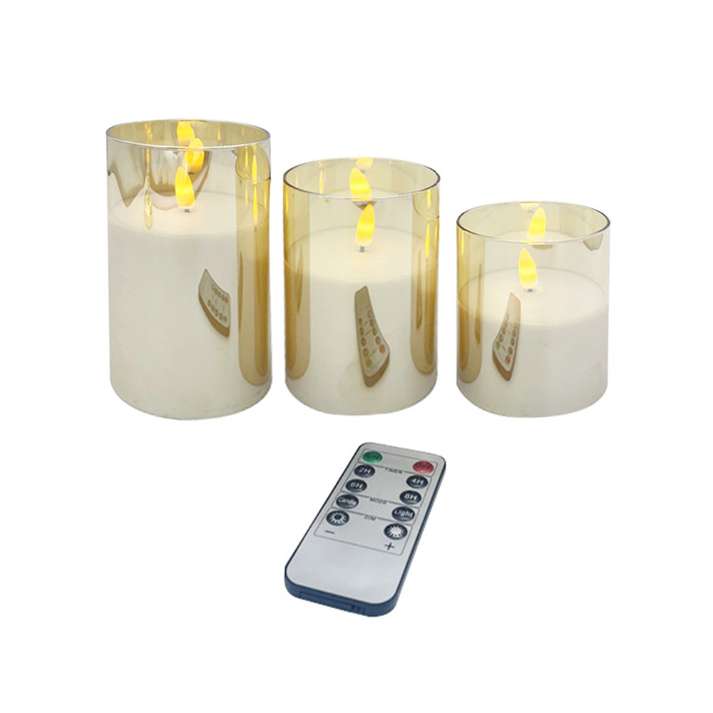
The device base includes a miniature infrared (IR) photo-diode or a low-power Bluetooth Low Energy (BLE) radio frequency (RF) transceiver. When an operator presses a button on a central remote control, the candle detects the wireless signal and switches modes instantly. This remote capability allows a single employee to turn on, dim, or configure automated sleep timers for thousands of separate candles across a large ballroom in seconds, saving significant labor time and protecting the units from handling wear.
Automated Timer Sequences and Sleep States
To conserve battery power automatically, the internal microprocessors include a low-power real-time clock circuit. Once activated by the operator, this circuit runs a repeating 24-hour routine—such as illuminating the candle for exactly 5 hours and then entering a deep sleep state for the remaining 19 hours. While in this sleep mode, the device powers down all non-essential circuits, dropping its current draw to under 15 micro-Amps to maximize battery life over weeks of unsupervised operation.
Outer Shell Materials and Optical Diffusion Geometry
The visual realism of an electronic candle depends heavily on the materials used for its outer shell, which must scatter the internal LED light just like real translucent paraffin wax.
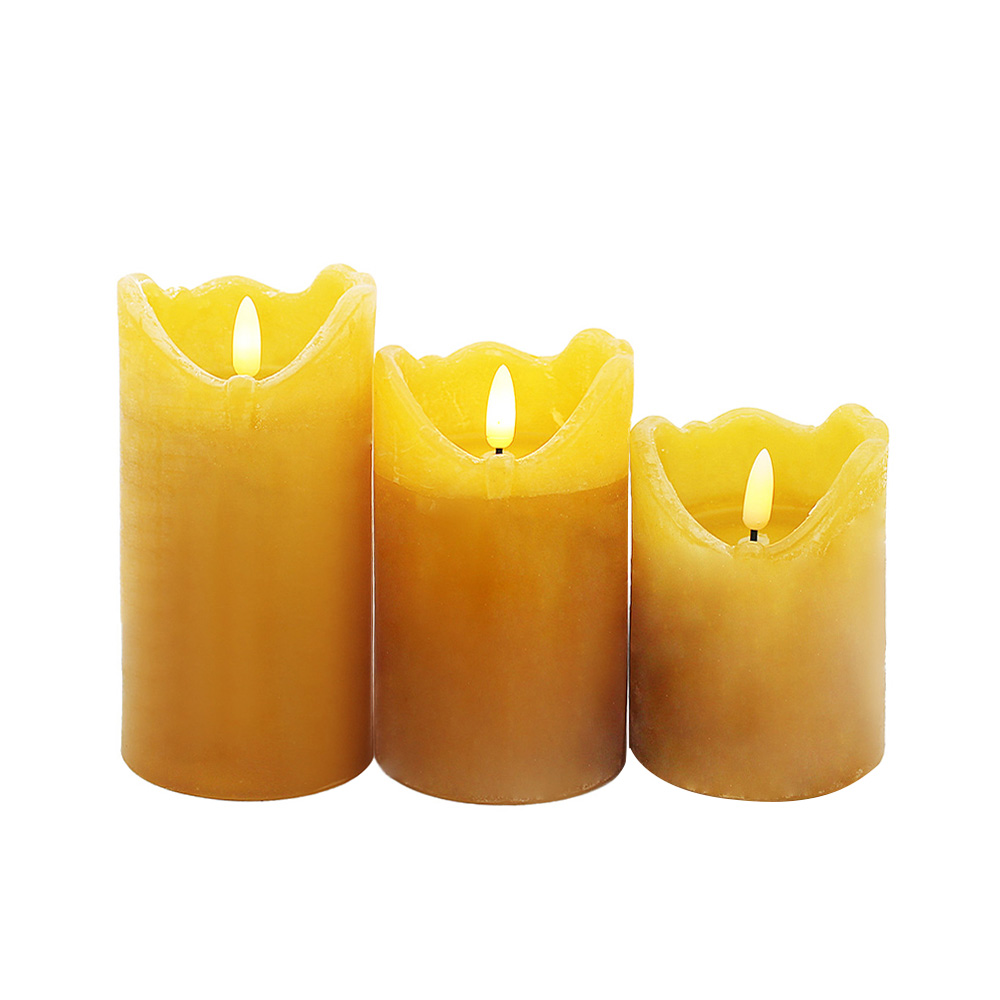
To achieve this look, premium electronic candles are cast inside an outer sleeve made from real paraffin wax or high-density polypropylene plastic blended with optical diffusion powders. When the internal LED fires, the light reflects off these embedded micro-particles, spreading a soft, warm glow throughout the upper third of the candle body. The top edge of the shell is often molded with an irregular, wavy contour that replicates the uneven melting pattern of a traditional burning candle, completing the visual illusion.
Step-by-Step Initial Setup and Fleet Charging Sequence
Deploying a multi-unit commercial electronic candle system requires following organized handling and charging protocols. Proper care and systematic charging prevent premature battery wear and ensure the entire fleet provides consistent, long-lasting illumination across every shift.
- Unpack and Inspect Component Shells: Carefully remove the candles from the shipping cartons and inspect the wax bodies for any cracks, surface scratches, or battery compartment alignment errors. Wipe the outer shells with a lint-free cloth to remove any dust or packing residue.
- Align Units on the Central Induction Charging Tray: Place the individual candles into the designated slots on a multi-port induction charging base. Ensure the bottom of each candle sits flat against the inductive coils, aligning the internal receiver loop with the tray's wireless power field.
- Connect Main Power and Monitor Charging Progress: Plug the main induction tray cord into a surge-protected electrical outlet. Verify that the indicator light on each candle base switches to a solid red or blue color, showing that the system has safely started its fast charging cycle.
- Verify Full Charge and Execute Wireless Syncing: Leave the fleet to charge for 4 to 6 hours until all status indicators turn green, showing the lithium batteries have reached full capacity. Grab the master infrared remote control, point it at the active array, and press the configuration keys to set the synchronized flicker speed and timer modes.
- Position Fixtures and Check Line-of-Sight Clearances: Distribute the candles across the venue's tables or wall sconces, keeping them out of direct heat vents that could soften real wax shells. Ensure the lower infrared sensor windows face out toward the main entry doors so the remote signal can reach them easily at closing time.
Root Cause Defect Diagnosis and Field Troubleshooting
When a commercial lot of electronic candles experiences a drop in runtime or fails to respond to remote commands, maintenance teams can quickly isolate and fix the problem by looking for specific electronic failure signs.
A common field issue is a candle that shuts off completely after only 2 or 3 hours of operation, despite sitting on the charging tray all day. This symptom is a classic sign of battery passivation or a failing charging connection. If a small amount of liquid or dust slips onto the charging base contacts, it can block the low-voltage current, preventing the battery from fully recharging. Technicians can resolve this by cleaning the metal terminal pins on both the base and the candle using a cotton swab dipped in isopropyl alcohol, clearing away foreign residues to restore clean electrical contact and full charging speeds.
Another frequent fault occurs when a group of candles ignores the master remote control while continuing to blink normally when switched on manually. This issue usually points to an optical signal blockage or localized ambient light interference. If an event uses high-power halogen spotlights or strong infrared room sensors, the intense external light beams can flood the candle's small IR receiver photodiode, blinding it to the remote's commands. To fix this, technicians should check the remote's battery levels, shield the candles from direct spotlight beams, or angle the remote transmitter directly at the candle bases to ensure a clear, uninterrupted control path.



 English
 Deutsch



 +86-18067520996
 +86-574-86561907
 +86-574-86561907
 [email protected]

 Wholesale Outdoor Flameless LED Candles Manufacturers
